COPY JAM
Beginning
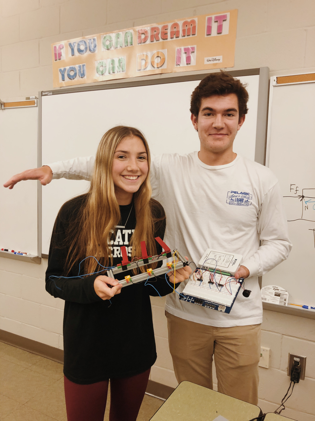
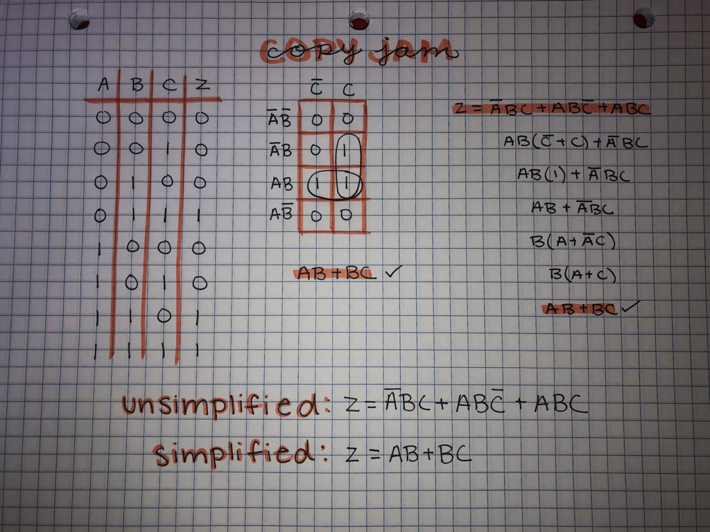
The Copy Jam Project purpose is to design a working prototype to identify when a copy machine had a paper jam. First we build the machines and found the simplified expression of the problem using truth tables, k- mapping and Boolean algebra. The using AOI logic circuits and flip flops we made a circuit on Multisim. Finally we built our circuit by bread boarding and wiring the light sensors to the board and buzzer and tested it to see if our design was correct.
Circuits
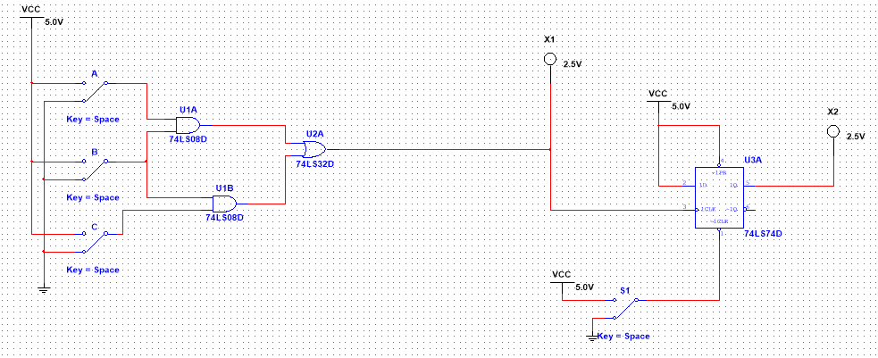
The Copy Jam project was more challenging then other projects because it included a flip flop in the combinational logic design. This made reading the wiring diagrams and bread boarding more difficult because we had to wire the pins in a different order then normally. However once we used the Multisim diagram we were able to get our circuit working easily along with out regular AOI logic.
Explanation of Parts
- Resistors: Used to power the input even when the light is off, it limits the current from power making the circuit on traveling through path of least resistance
- Combinational logic circuit: Tells the buzzer and LED when to sound when the inputs are on and off
- Flip flop: Used as an event detector, when the buzzer sounded we could turn the switch off, turning the buzzer off
- The LED: Goes off when its inputs, or phototransistors change however, the buzzer will stay on because it is attached to Q, which wants to be like D which is on, therefore the only way to turn off the buzzer is to clear it
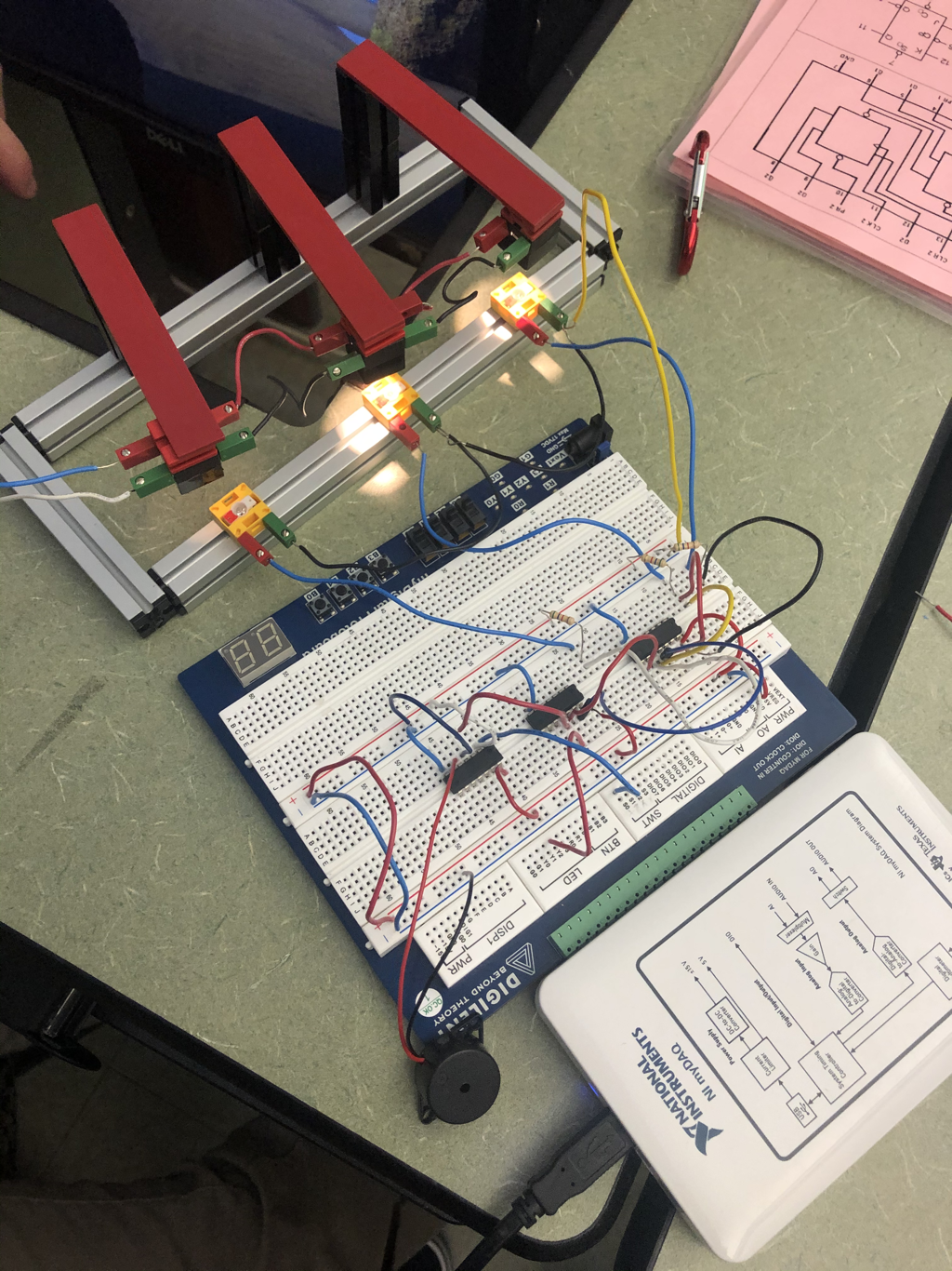
Conclusion
This project was much more difficult than others, because we had implement a flip flop chip and had to build a fischertechnik kit as our testing machine. Building this machine took lots of our time and was a a struggle to use because all of the wires kept falling out but we eventually made it through, after learning how to wire our circuit to the actual machine which we relied on as a power source to our circuit. We also had to wire our flip flop chip which we had never done before so we had to learn the pin set up and follow the Multisim design to properly wire it. The flip flop set up allowed us to use a buzzer alarm which was new to us as well, learning how to wire new components helped our circuit to function and alert us when there was a copy jam!
