MAJORITY VOTE
|
|
Project Overview
The purpose of the Majority Vote Project is to design an electronic voting machine, with a circuit to show whether or not a decision will pass or not. The board of directors has 4 people who get to vote on the decision, the President, Vice President, Secretary, and Treasurer. For the decision to pass the majority (3/4) must vote "yes" however, if there is a 2-2 tie the decision will pass if the President votes "yes". When creating the circuit we were only allowed to use AOI logic with two-input gates and a breadboard for our functioning circuit.
Truth Table and Un-simplified Expression
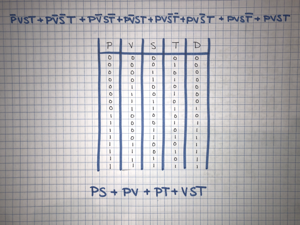
The truth table breaks down and lists all of the possible combinations and outcomes. In this project there were 4 variables, President, Vice President, Secretary, and Treasurer (P, V, S and T), there were 16 rows because of the relationship of 2^n, with n being the number of rows. 2^4 is 16 and therefore there are 16 rows for possible combinations. When creating a truth table we used numbers 0 and 1 to tell us if they voted yes(1) or if they voted no(0). The decision will either be not passed(0) or passed(1), which is recorded in the last column (D)based on the variables. In the event of a tie 2-2 the table shows that each time the President is voting yes in a tie, the vote passes based of his vote. From the table we can identify our minterms with create our un-simplified equation.
The un-simplified equation is a sum of products form (SOP). In our truth table there are 8 different combinations or minterms that pass the decision. Using the assignment conditions and 1's and 0's in the table we could tell if they voted yes or no and what the presidents vote was to determine the outcome. If the member voted "yes" then their variable in the minterm is left alone, if they voted "no" then their variable has a line above it to represent that they did NOT vote yes. The SOP form is better than the POS form because it shows each individual outcome/combination that works to get the decision to pass.
The un-simplified equation is a sum of products form (SOP). In our truth table there are 8 different combinations or minterms that pass the decision. Using the assignment conditions and 1's and 0's in the table we could tell if they voted yes or no and what the presidents vote was to determine the outcome. If the member voted "yes" then their variable in the minterm is left alone, if they voted "no" then their variable has a line above it to represent that they did NOT vote yes. The SOP form is better than the POS form because it shows each individual outcome/combination that works to get the decision to pass.
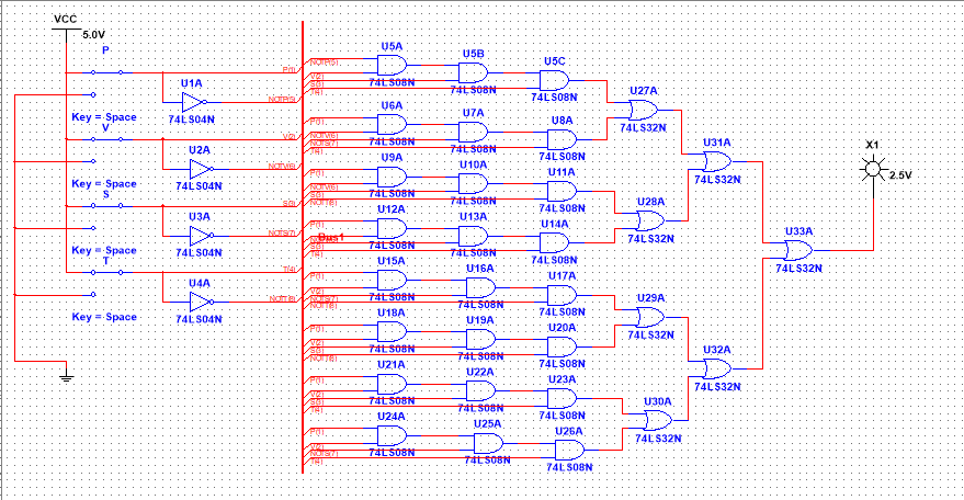
Un-simplified Circuit
When creating the un-simplified circuit I used the bus method to keep all of my wires organized and efficient. I used the un-simplified equation and truth table to create the circuit starting with each of my input variables(P,V,S and T). Then I used the three different gates, inverter, AND and OR to create each minterm. The inverter gate changes the variable from x to not x, or not x to x, the AND gate combines two variables by multiplication and finally the OR gate that combines variables by addition. I needed 4 inverters, 24 AND gates and 7 OR gates. There are 4 gates in each chip so I would need 9 chips to make this circuit by bread-boarding.
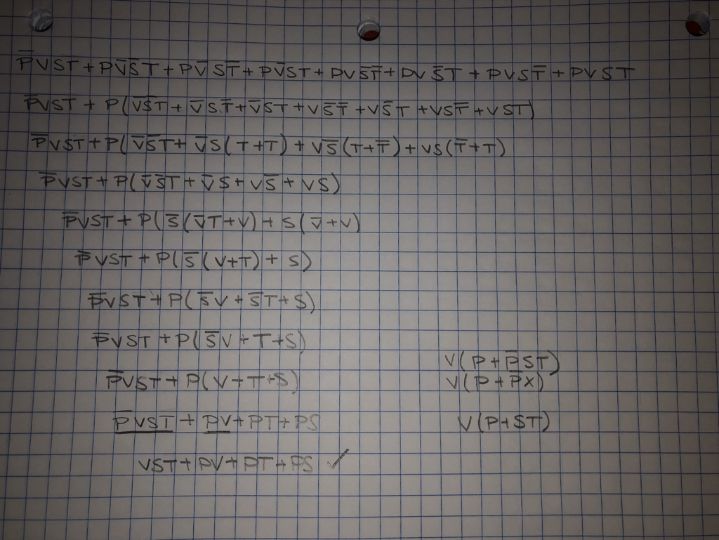
Boolean Algebra Simplification
We used Boolean Algebra to simplify the complicated un-simplified expression, making it easier to wire and more efficient. We went from 8 four variable minterms, to 3 two variable minterms and 1 three variable minterm.
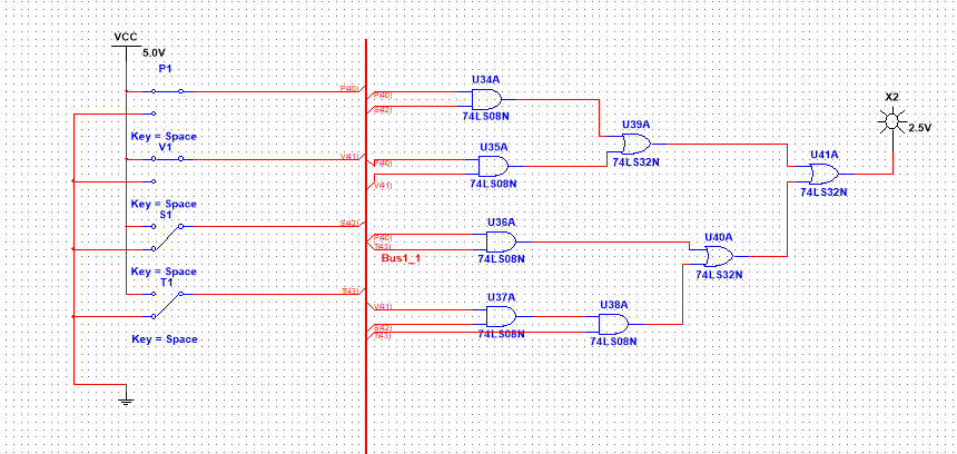
Simplified Circuit
When creating the simplified circuit I again used the bus method to keep all of my wires organized and efficient. I didn't use a resistor in my schematic of the simplified circuit, but the resistor would be used to restrict some of the energy from flowing through so that the LED doesn't burn. The Boolean Algebra simplified the expression and cut down the amount of gates. Now there is no need for inverter gates, only 5 AND gates and 3 OR gates. This also decreased the amount of chips from 8 to 3 chips, 2 for the AND gates and 1 for the OR gates.
The simplified circuit used less gates and chips than the un-simplified circuit. The original used 35 gates now there are only 8, 27 less gates. The original also used 9 chips and now only uses 3, 6 less. The simplified circuit uses less materials to be made and is more efficient and quicker to wire the breadboard than the un-simplified.
The simplified circuit used less gates and chips than the un-simplified circuit. The original used 35 gates now there are only 8, 27 less gates. The original also used 9 chips and now only uses 3, 6 less. The simplified circuit uses less materials to be made and is more efficient and quicker to wire the breadboard than the un-simplified.
Bill of Materials
|
The Bill of Materials includes of all the required materials and components needed to create the working circuit.
|

|
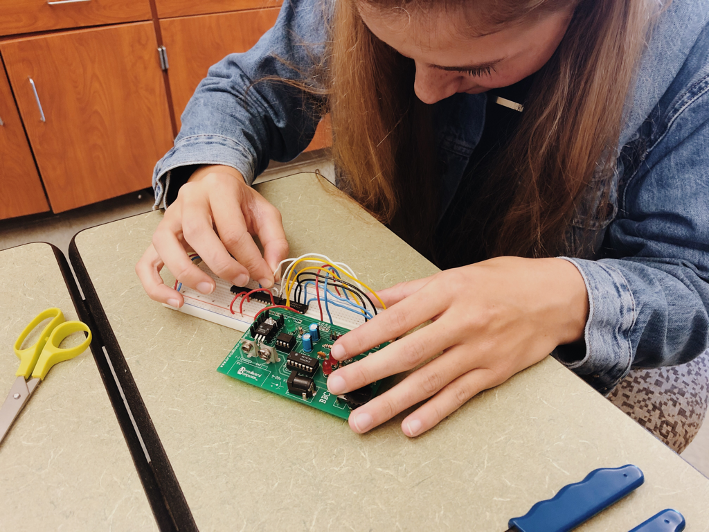
Bread-boarding
These three pictures are the various stages of bread-boarding that I did in class. In picture 1, I first added the breadboard companion to the top corner of the board and connected the 5V to the positive bus and the 0V to the negative bus, I also bridged both positive and negative buses at the bottom of the board. After placing my two AND gates (74LS08) and my OR gate (74LS32) I connected each 14 pin to the positive bus and each 7 pin the the negative bus. Then, in picture 2 you can see I began wiring my minterms, I used blue wire for PV, black for PS, red for PT, and white for VST. I wired all of my inputs leaving the outputs open and connected VS to T. Finally in picture 3 I connected my outputs for both AND gates into the OR gate and connected my resistor and LED.
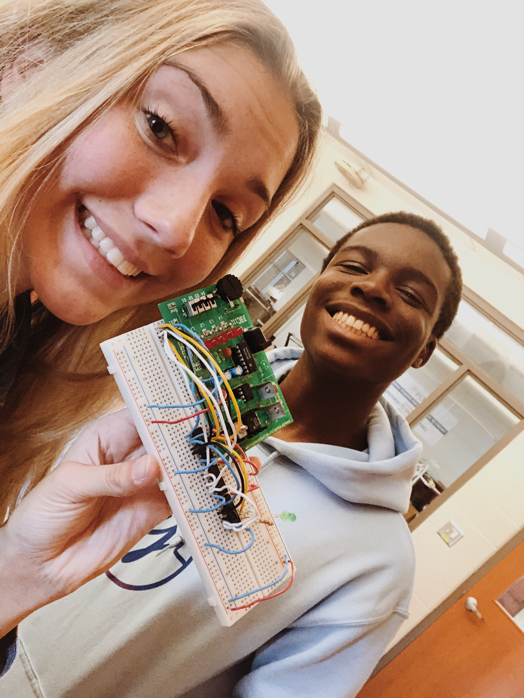
My first bread-boarding experience was challenging, but I really enjoyed it! I learned it is key to take your time and to color code your wires! I made sure all of my wires corresponded to the bus they were in (positive or negative), and also troubleshooted after each step making sure I did everything right before I moved on. I did color code every minterm which was very helpful, other classmates used all one color and when troubleshooting their own work got stuck and frustrated. However, when I went up to check my circuit, all I had to adjust was the placement of the resistor, connecting it to the final output and it worked! Taking my time, checking my work as I went and color coding help me stay organized and allowed my to get it done right the first time!
My first bread-boarding experience was challenging, but I really enjoyed it! I learned it is key to take your time and to color code your wires! I made sure all of my wires corresponded to the bus they were in (positive or negative), and also troubleshooted after each step making sure I did everything right before I moved on. I did color code every minterm which was very helpful, other classmates used all one color and when troubleshooting their own work got stuck and frustrated. However, when I went up to check my circuit, all I had to adjust was the placement of the resistor, connecting it to the final output and it worked! Taking my time, checking my work as I went and color coding help me stay organized and allowed my to get it done right the first time!
Final Project Conclusions
I really enjoyed this project, at times it was very frustrating and challenging but it was so worth it when the circuit worked and the LED came on! This project taught me a lot about the process of circuiting and showed me that patience is key and slow and steady wins the race, not only with bread-boarding, but with Boolean algebra too. Beginning with the problem statement and knowing I had to design and create an electronic voting machine, I first had to make a truth table. With my truth table I found my un-simplified expression and created it on multisim. Then I used Boolean Algebra to simplify my expression and created the simplified expression on multisim as well. Finally, I began to bread-board my circuit, I gathered my materials and connected all of my wires to the chips to match m y minterm values and it worked! The Boolean Algebra step is probably the most important because you get your simplified expression, which has the smallest possible equivalent minterms. By simplifying you expression you save yourself the time and materials. Creating the simplified expression was stressful enough I can not imagine trying to wire 8 different minterms, using more wires and creating a bigger mess which would only make trouble shooting harder. Therefore, the Boolean Algebra is the most important step in the process reducing your expression going from a problem statement to a functioning circuit mush faster and easier.
