Project overview

|
|
The purpose of this project was to create a light up seven segment display to show our date of birth. To do this we used our birthdays to make a truth table corresponding with the seven segments, a through g.Then we used K mapping instead of Boolean Algebra to find the simplest logic expression and created our simplified circuit on Multisim. The circuit must must use a common cathode for our seven-segment display, 150 ohms to 270 ohms resistor, and one segment should be displayed using only NAND and one with only NOR. Finally we breadboarded our circuits to display our date of birth on the seven segment display.
Truth table
The truth table is used to show all possible combinations of the X, Y and Z inputs for our displays to either turn on or off. We use the logic expressions to show which of the seven segments in the common cathode will illuminate during the correct time when displaying our birth dates.
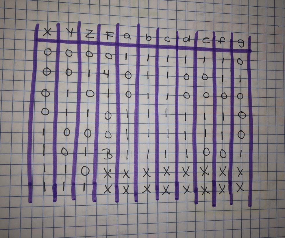
The input values of my truth table are XYZ and the numbers from my birthday determine the output values (04/10/03). There are 7 columns labeled a-g because they correspond with the 7 segments in the common cathode and form the number of my birthday. The segment is on when there is a 1, and is off when the ere is a 0. The x's for the bottom two rows are a "don't care condition" they do not effect my birth date and can be used as a 1 or a 0.
Karanaugh Maps and simplified logic for each of the seven segments
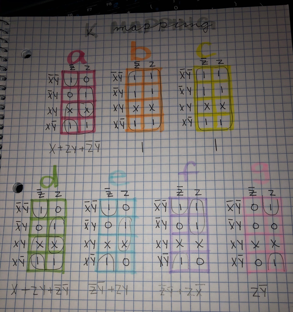
When K mapping you begin with creating a chart based off the variables in your truth table, for this project X and Y are on the left and Z is on the top. Then you fill out the K-map rows using the Display values going from left to right in the chart, the 1st pair, then 2nd, 4th, then third. Then you group the "1's" and x's if needed, to create 1,2,4,8 or pac-man to get the expression for each segment. These logic expressions are written in sum of products form because it is easier to draw and trace the AOI logic circuit. I had 7 k maps, one for each segment of my common cathode and all were simplified. In the end I had 2 matching sets, for one of them the output was 1, because all the variables would cancel, causing the circuit to be always on. K-mapping is much more efficient than Boolean algebra the minterms are much more organized and it is much faster to circle 1's them to simplify the un-simplified logic expression.
MultiSim implementation
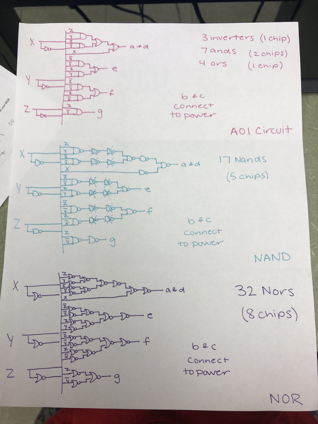
The image below is the wiring of my circuit on the Multisim program, one circuit fo reach of my sengemts a- g. There are a mix of NAND, NOR and AOI circuits, which are all attached to resistors and the common cathode.
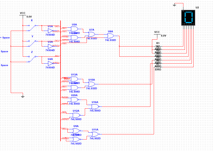
I created my circuit in bus form to make it easier and more efficient to wire. To create this circuit I needed 3 inverter gates, 4 AND gates, 3 OR gates, 3 NAND gates, and 3 NOR gates, therefore I needed 5 chips, one of each type. We use NAND and NOR gate in our design to limit the amount of gates need in the the circuit, however it does not always help. For example, for segment g if you were to use a regular AND gate you would only need 1, but you would need 3 NAND gates. But for segment f you would need 2 AND gates and 1 OR gate, but I used 3 NOR gates and it was more efficient because it only requires 1 chip instead of 2, decreasing the price of materials for that circuit. The seven segment display works by wiring a circuit to connect into each segment (A-G). There are two types of displays; common cathode and common anode. We used common cathode in this project because each segment is wired to ground so for the wires you wish to turn on you must wire them to power. Common anode is reversed, it is wired to power and the segments must be wired to the ground to work. We used common cathode in this project because the digital logic board is setup with common cathode. The resistors in the circuit limit the current going into the seven segment display, making sure the power is not too strong in the display.
Bill of materials
The Bill of Materials shows the amount of each component that was used in the creation of my circuit.

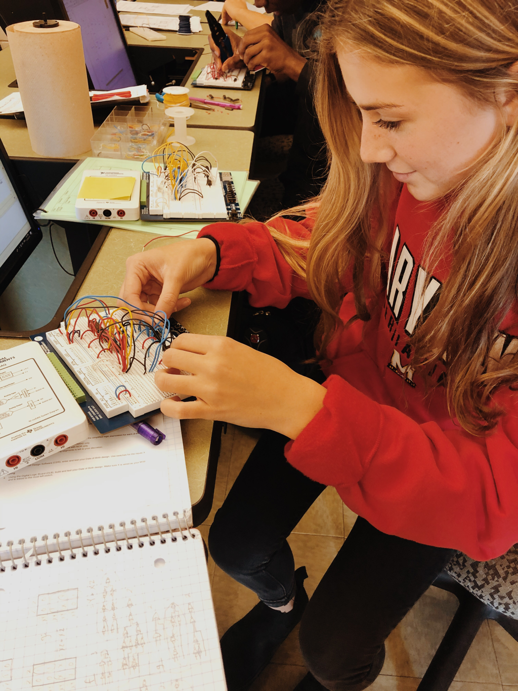
Breadboarding
My second bread-boarding experience was challenging because there were more circuits and wires, but I it was much easier because I knew what I was doing and each step to take. The key really is to take your time and to color code your wires! Color coding every minterm was very helpful when tracing each individual segment circuit one at a time. Other classmates used all one color and when troubleshooting their own work got stuck and frustrated, so I made sure after each step I did everything right before I moved on to the next segment. I again made sure all of my 14 and 7 pins were wired to their corresponding bus (positive or negative), and that my wires were in the correct pins, especially the NOR gate because it's input and output pins are reversed. However, as I checked each circuit I kept getting confused when my switches were on and off, but I sorted it all out! When I checked my circuit it worked perfectly, I just had to make sure my chips were completely pressed into place. Taking my time, checking my work as I went, and color coding helped me stay organized and allowed my to get it done right the first time!
Conclusion
I really enjoyed this project, becoming more familiar with the multisim program and become more comfortable with wiring my breadboard. I have realized that my organization skills really come in handy when I am wiring, color coding is KEY! This project also introduced us to NAND and NOR gates so I was able to learn how to wire each gate, and that NOR pins are reversed. If we were to do this project again I would give myself more time on Multisim, and maybe spread out my chips more so would have more space to work. I also learned that retracing after each step and talking my way through wiring is REALLY helpful, I might sound crazy as I do it but it works! Is there a way to only use the MIltisim file to power a chip and run the program in a real life display?
Extra credit
|
The basic design of my circuit is the most efficient in the AOI design, it uses 4 chips total ( 3 different gates) compared to 5 NAND chips and 8 NOR chips).
|
|
